Modeling Capabilities with Model-Based Systems Engineering (MBSE)
Model-based systems engineering (MBSE) as a methodology does not directly address capabilities, which describes the abilities of a system to achieve or perform a task or a mission. As a part of a problem description, capabilities have a strong connection to system requirements, and can be modeled using similar approaches. In the SEI Blog post Requirements in Model-Based Systems Engineering (MBSE), I discussed the requirements domain. In this post, I consider the role of capabilities in system engineering—their purpose, how they are modeled and analyzed using MBSE and SysML, and how they can be associated with business requirements.
Capability is an overloaded term. There are business capabilities and technical capabilities from the business architecture domain, solution capabilities from the systems development process domain, such as scaled agile framework (SAFe), and just capabilities from the Unified Profile for DoDAF/MODAF (UPDM) or Unified Architectural Framework (UAF). These definitions essentially fall into two types: (1) a high-level concept describing an ability of a system to achieve or perform a task or a mission and (2) a technical concept describing a solution for a specific business problem. In this blog post, I focus on the first type of capability, a high-level concept that I will refer to as just capability.
Product or project managers often consider the capabilities of a future or existing system when considering the system’s vision and roadmap. Capabilities provide a comprehensive picture in the absence of implementation details. Like requirements, capabilities are elements of the problem description. Capabilities and requirements are tightly connected, and they inform and refine each other. Business experts often define stages of the business process by first answering the question, What should the system be able to do? From there, the capabilities emerge.
For example, M. Maier in his 1998 article, “Architecting Principles for System-of-Systems” described intelligent transport systems (ITS) as an example of a system of systems. as According to Maier, the business vision for such systems is to
- provide “real-time information on graphic conditions and transportation options to travelers in any location”
- “allow a traveler to scan traffic conditions and choose the transportation mode with predicted least travel time”
- “allow a wide range of traffic control strategies to be applied across metropolitan areas using strategies optimized from the information available”
- use information that “could include real-time and predictive estimation of link times throughout the traffic network”
- use information that could include “real-time statistics on driver start–destination points and planned route”
From this business vision, several capabilities could be extracted, including
- traveler management
- travel-condition management
- traffic-controls management
- information management
- route management
- traffic-control strategies management and optimization
- communication management
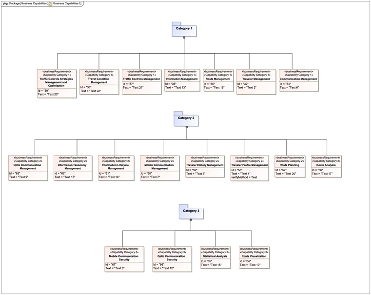
MBSE explicitly offers a means to model requirements, but does not provide capabilities as an element type. There is a business requirement element (see my post Requirements in Model-Based Systems Engineering) that can be used to model the system’s capabilities, as shown in Figure 1 below.

As with many high-level elements in systems engineering, capabilities require decomposition. Articles in Modern Analyst, Capstera, and the Business Technology Architecture Body of Knoweldge state that there can be up to five levels of capabilities, with the number of levels depending on the size and complexity of the system. Complex systems of systems may require all five levels plus one sub-level, capable of. The example in Figure 2 uses only three levels of capability decomposition and calls these levels categories. Capabilities can be organized based on other principles, such as functional areas or enterprise structure. Using package structure, custom stereotypes, and color coding can help systems engineers and business or enterprise architects better organize capability decomposition.
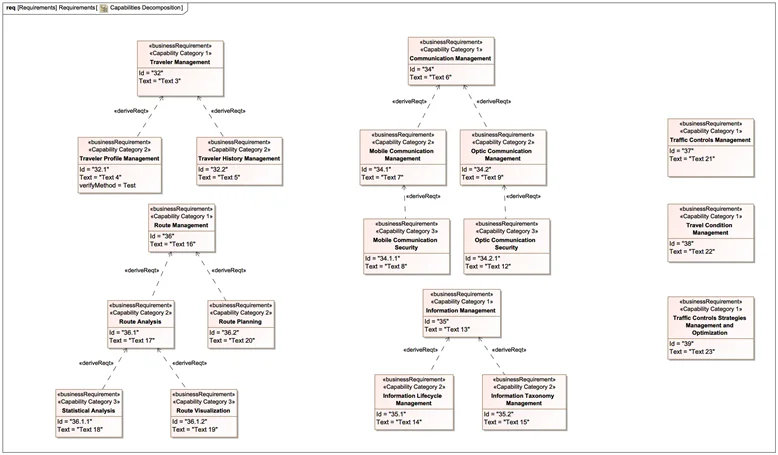
If package structure is used to organize a system’s capabilities, the derive relationship shows decomposition of the capabilities from different packages representing levels as shown in Figure 3. For visually tagging capabilities from different categories, custom stereotypes can be helpful.
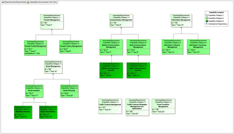
As shown in Figure 4, a combination of custom stereotype, color coding, and child–parent relationship can also organize capabilities without separating them into different packages.
One role of capabilities is to cover what an enterprise or a system does without requiring decomposition into the details. Details that include a user view of the functionality or constraints come from requirements. A good model should offer a connection between capabilities and requirements. Instead of deriving the relationship between capabilities represented as business requirements and other requirements (as I showed in the SEI blog post Requirements in Model-Based Systems Engineering (MBSE)), the looser trace relationship can be used, as shown in Figure 5.
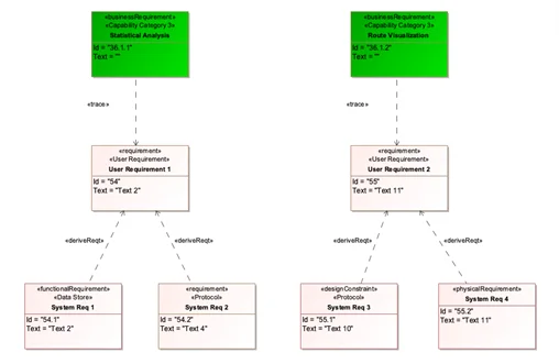
Connecting capabilities to requirements creates a vital linkage between two different types of conceptual problem description that helps manage the complexity of the system. By staying at a high level of abstraction, capabilities allow an architect to plan phases of the system evolution without the need to keep many details in mind. Those details will not be lost if they are captured as requirements and traced to a corresponding capability.
There is one key difference between capabilities and requirements: Requirements come from different sources, sponsored by different stakeholders, and are usually captured at different levels of abstraction. In contrast, capabilities should always represent a coherent and consolidated view of the system or enterprise.
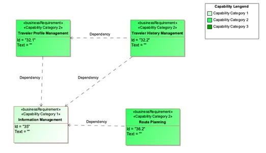
After they are captured and decomposed, capabilities must be analyzed. One type of analysis is to identify dependencies between capabilities. Even though two capabilities can belong to two different areas of the system, one can depend on another, as shown in Figure 6 below. The nature of the dependencies can also differ. A capability can depend on another capability functionally because of a business process, order of operations, or data passing.
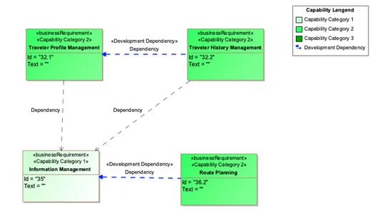
On the other hand, one capability can be an extension of another capability using an already existing functionality of the system. Such capabilities should be developed in an appropriate order, as shown in Figure 7 below. The dependency relationship captures this fundamental information in the model and ensures that it will be delivered to the next phase of the system-development lifecycle.
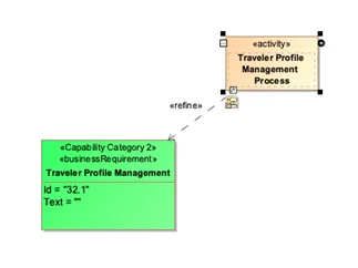
Capabilities by themselves are not sufficient for an understanding of how a system or enterprise will function. They must be augmented by an explanation of how a system will behave when it exhibits those capabilities. Even when we stay at a high level of abstraction, we need to analyze the behavior of the system or enterprise at that level. A Systems Modeling Language (SysML) activity diagram is a way to capture behavior in the form of a process. A relationship to use for associating capability and activity is refine, as shown in Figure 8 below.
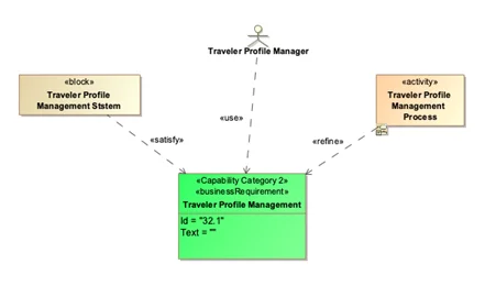
As a part of capability analysis, an architect often starts to think about a part of a system or modules that will perform the capabilities under analysis as well as users and the roles that humans will play while interacting with the system or as a part of the enterprise. Here the activity and block SysML elements could help, as shown in Figure 9 below.
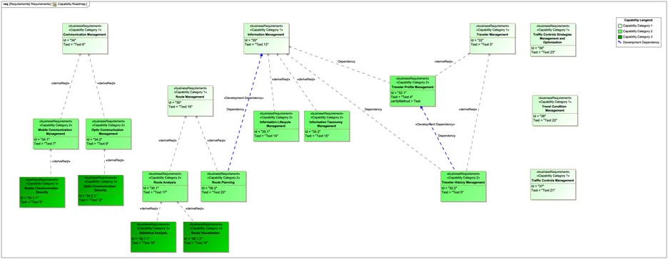
When an enterprise architect finishes decomposition and analysis of the capabilities, the next logical step is to create a roadmap for capabilities development and a release including phasing for capabilities. For this, SysML does not provide any specialized tool. All relationships captured by the model along with standard analysis will help an architect find a critical path for delivering a capability and defining the roadmap, as shown by the example in Figure 10 below.
Observations and Conclusions
SysML has a few deficiencies in its support of the enterprise and portfolio architecture that can be overcome with help of architectural frameworks:
- SysML does not support capabilities by default.
- An architect will need to create additional stereotypes and an enforcement mechanism to accommodate capabilities.
- SysML does not support creation of a roadmap for the capabilities, including planning over time.
In theory, it would be possible for an experienced enterprise architect to create a custom meta-model to implement to some degree one of the standard architectural frameworks, such as The Open Group Architecture Framework (TOGAF) or DoD Architecture Framework (DoDAF)/Unified Architecture Framework (UAF) using just SysML. Doing so, however, would be time-consuming and yield a barely usable result. Such a meta-model would be complex, hard to implement and follow, and hard to enforce without complicated model-verification rules that would be challenging to create. A better option would be to look at existing extensions of SysML that implement an architectural framework of choice. All major providers of MBSE/SysML modeling environments support the most popular architectural frameworks.
Modeling capabilities that use MBSE address several critical aspects of building a system of systems. Capability modeling helps systems engineers manage the complexity and volume of requirements by abstracting specific characteristics of the system. This level of abstraction also facilitates communication among stakeholders and helps create the project roadmap. By helping to produce well analyzed and understood capabilities, modeling supports the creation of a better system and enterprise architecture. MBSE practices support traceability of capabilities to requirements as well as traceability of capabilities to operational and logical architecture transitively to solution architecture. Increased traceability improves the quality of the system and ensures confidence that the system will be built according to requirements.
Additional Resources
Read the SEI blog post, An Introduction to Model-Based Systems Engineering (MBSE).
Read the SEI blog post, Requirements in Model-Based Systems Engineering (MBSE).
Read SEI blog posts about MBSE.
Read SEI blog posts about digital engineering.
Register for our Secure Software by Design Workshop in Arlington, VA, June 12-13, 2023.
More By The Author
More In Software Architecture
PUBLISHED IN
Get updates on our latest work.
Sign up to have the latest post sent to your inbox weekly.
Subscribe Get our RSS feedMore In Software Architecture
Get updates on our latest work.
Each week, our researchers write about the latest in software engineering, cybersecurity and artificial intelligence. Sign up to get the latest post sent to your inbox the day it's published.
Subscribe Get our RSS feed
