How to Use Docker and NS-3 to Create Realistic Network Simulations

Sometimes, researchers and developers need to simulate various types of networks with software that would otherwise be hard to do with real devices. For example, some hardware can be hard to get, expensive to set up, or beyond the skills of the team to implement. When the underlying hardware is not a concern but the essential functions that it does is, software can be a viable alternative.
NS-3 is a mature, open-source networking simulation library with contributions from the Lawrence Livermore National Laboratory , Google Summer of Code, and others. It has a high degree of capability to simulate various kinds of networks and user-end devices, and its Python-to-C++ bindings make it accessible for many developers.
In some cases, however, it's not sufficient to simulate a network. A simulator might need to test how data behaves in a simulated network (i.e., testing the integrity of User Datagram Protocol (UDP) traffic in a wifi network, how 5G data propagates across cell towers and user devices, etc. NS-3 allows such kinds of simulations by piping data from tap interfaces (a feature of virtual network devices provided by the Linux kernel that pass ethernet frames to and from user space) into the running simulation.
This blog post presents a tutorial on how you can transmit live data through an NS-3-simulated network with the added advantage of having the data-producing/data-receiving nodes be Docker containers. Finally, we use Docker Compose to automate complex setups and make repeatable simulations in seconds. Note: All the code for this project can be found in the Github repository linked at the end of this post.
Introduction to NS-3 Networking
NS-3 has a number of APIs (application programming interfaces) to make its simulations interact with the real world. One of these APIS is the TapBridge class, which is essentially a network bridge that allows for network packets coming in from a process to become available to the NS-3 simulation environment. It does this by sending traffic to a Linux Tap device sent over to the NS-3 simulation. In the C++ code below, we can see how easy it is to use to use the TapBridge API:
// Create an ns-3 node
NodeContainer node;
node.Create(1);
// Create a channel that the node connects to
CsmaHelper csma;
NetDeviceContainer devices = csma.Install(node);
//Create an instance of a TapBridge
TapBridgeHelper tapBridge;
// Enable UseBridge mode, which has the user define the tap device it will
//connect to. There are more modes available which we won’t discuss here.
tapBridge.SetAttribute("Mode", StringValue(“UseBridge"));
// we are defining our tap device which I called mytap
tapBridge.SetAttribute("DeviceName", StringValue("mytap"));
tapBridge.Install(node.Get(0));
}
The code above assumes that the user created a named Tap Device (“mytap”) and that the TapBridge instance can connect to it.
Since simulations commonly feature multiple users, we can envision each user as its own, isolated node that produces and transmits data into the simulation. This scenario therefore fits well within the model of running multiple containers within the same host. A container is simply an isolated process with its dependencies separated from its surrounding environment, using special Linux Kernel application programming interfaces (APIs) to accomplish this. The following diagram sketches out the setup I’d like to create for the first iteration of this tutorial:
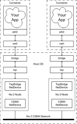
Two containers are each running some kind of data-producing application. That data is broadcasted through one of its network interfaces into the host running the NS-3 simulation using a bridge. This bridge glues together the container network with the tap device interfaces on the host by using veth (virtual ethernet) pairs. This configuration enables sending data to the listening node in the NS-3 simulation. This setup frees us from having to stand up multiple VMs or applications that share dependencies and enables portability and maintainability when running NS-3 simulations across different machines.
The first iteration of this tutorial uses Linux Containers (LXC) to implement what was shown in the figure above, and closely follows what the NS-3 wiki already shows, so I won't dwell too much on it.
LXC doesn’t carry much overhead, making it relatively easy to understand, but LXC lacks a lot of the functionality you'll find in the aforementioned container engines. Let’s quickly create the setup shown in the diagram above. To start, ensure NS-3 and LXC are installed in your system and that NS-3 is built.
1. Create Tap Devices
ip tuntap add tap-left mode tap
ip tuntap add tap-right mode tap
2. Bring up taps in promiscuous mode (This mode tells the OS to listen to all network packets being sent, even if it has a different MAC destination address.):
ip link set tap-left promisc on
ip link set tap-right promisc on
3. Create network bridges that will connect the container to the tap device:
ip link add name br-left type bridge
ip link add name br-right type bridge
ip link set dev br-left up
ip link set dev br-right up
4. Create the two containers that will ping each other:
lxc-create -n left -t download -f lxc-left.conf -- -d ubuntu -r focal -a amd64lxc-create is the command to create containers but not to run them. We specify a name (-n) and a configuration file to use (-f) and use one of the pre-built template (-t) —similar to a Docker image. We specify the container to use the ubuntu (-d) focal release (-r) in amd64 architecture (-a). We do the same command but for the “right” container.
5. Start the containers:
lxc-start left
lxc-start right
6. Attach to the containers and an IP address to each:
(in a new shell)
lxc-attach left
#left >ip addr add 10.0.0.1/24 dev
(in a new shell)
lxc-attach right
#right >ip addr add 10.0.0.2/24 dev
Confirm that the IP addresses have been added using
ip addr show7. Attach tap device to the previously made bridges (note: the containers will not be able to connect to each other until the simulation is started).
ip link set tap-left master br-left
ip link set tap-right master br-right
8. Start the NS-3 simulator with one of the example tap device programs that come with NS-3:
./ns3 run ns-3/src/tap-bridge/examples/tap-csma-virtual-machine.cc9. Attach to each container separately and ping the other container to confirm packets are flowing:
#lxc-left >ping 10.0.0.2
#lxc-right >ping 10.0.0.1
Connecting NS-3 to Docker
This bare-bones setup works well if you don't mind working with Linux containers and manual labor. However, most people don't use LXC directly, but instead use Docker or Podman. Developers often think that the setup for Docker would be similar: create two Docker containers (left, right) with two Docker network bridges (br-left, br-right) connected to each other like so:
docker run -it --name left --network br-left ubuntu bash
docker run -it --name right --network br-right ubuntu bash
Then attach tap devices to the network bridge’s id (The network bridge id can be retrieved by running ip link show):
ip link set tap-1 master br-***
ip link set tap-2 master br-***
This setup unfortunately, does not work. Instead, we will have to create a custom network namespace that acts on behalf of the container to connect to the host network interface. We can do this by connecting our custom network namespace to the container ethernet network interface by using veth pairs, then connecting our namespace to a tap device via a bridge.
- To start, create custom bridges and tap devices as before. Then, allow the OS to forward ethernet frames to the newly created bridges:
sudo iptables -I FORWARD -m physdev --physdev-is-bridged -i br-left -p tcp -j ACCEPT
sudo iptables -I FORWARD -m physdev --physdev-is-bridged -i br-left -p arp -j ACCEPT
sudo iptables -I FORWARD -m physdev --physdev-is-bridged -i br-right -p tcp -j ACCEPT
sudo iptables -I FORWARD -m physdev --physdev-is-bridged -i br-right -p arp -j ACCEPT
2. Create the Docker containers and grab their Process ID (PID) for future use:
pid_left=$(docker inspect --format '{{ .State.Pid }}' left)
pid_right=$(docker inspect --format '{{ .State.Pid }}' right)
3. Create a new network namespace that will be symbolically linked to the first container (this is setting us up to allow our changes to take effect on the container):
mkdir -p /var/run/netns
ln -s /proc/$pid_left/ns/net /var/run/netns/$pid_left
4. Create the veth pair to connect containers to the custom bridge:
ip link add internal-left type veth peer name external-left
ip link set internal-left master br-left
ip link set internal-left up
5. Assign an IP address and a MAC address:
ip link set external-left netns $pid_left
ip netns exec $pid_left ip link set dev external-left name eth0
ip netns exec $pid_left ip link set eth0 address 12:34:88:5D:61:BD
ip netns exec $pid_left ip link set eth0 up
ip netns exec $pid_left ip addr add 10.0.0.1/16 dev eth0
6. Repeat the same steps for the right container, bridge, and interfaces.
7. Head over the containers and start them with a TTY console like bash.
8. Finally, start the NS-3 simulation. Ping each container and watch those packets flow.
This setup works at Layer 2 of the OSI Model, so it allows TCP, UDP, and HTTP traffic to go through. It is brittle, however, since any time the container is stopped, the PID is thrown out, and the network namespace we made becomes useless. To reduce toil and make this process repeatable, it is better to use a script. Better yet, if there were a way to orchestrate multiple containers so that we can create an arbitrary number of them—with scripts that kick off these configurations and stop the running containers—we could have an incredibly useful and portable tool to run any kind of simulation using NS-3. We can take this process one step further using Docker Compose.
Using Docker Compose to Automate our Simulations
Let's take a step back and review our levels of abstraction. We have a simulation that is running a scenario with n number of containers, some sending and receiving messages and one that runs the simulation itself. One can imagine having more containers doing certain tasks like data collection and analysis, etc. After the simulation ends, an output is produced, and all containers and interfaces are destroyed. The following schematic illustrates this approach:
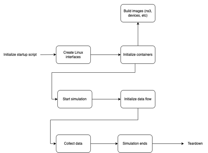
With this level of abstraction, we can think at a high level about what the needs of our simulation are. How many nodes do we want? What kind of network do we want to simulate? How will the data collection, logging, and processing take place? Defining the first and then going into the granular level later allows for easier conceptualization of the problem we are trying to solve, and also takes us to a level of thinking that tries to get closer to the problem.
To make this concrete, let’s examine the following Docker Compose file in detail. It defines the simulation to be run as two devices (“left” and “right”) that communicate over a point-to-point connection.
For each user-end device (in this case, “left” and “right”) we define the OS it uses, the network mode it operates on and an attribute to enable us to log into the shell once they’re running.
“ns_3” uses a custom image that downloads, builds and runs NS-3 along with the 5G-Lena package for simulating 5G networks. The image also copies a development file for NS-3 from the host environment into the container at the appropriate location, allowing NS-3 to build and link to it at runtime. To access kernel-level networking features, the NS-3 container is granted special permissions through “cap-add” to use TapDevice interfaces, and a network mode of “host” is used.
version: "3.8"
services:
  left:
    image: "ubuntu"
    container_name: left
    network_mode: "none"
    tty: true
    depends_on:
      - ns_3
  right:
    tty: true
    image: "ubuntu-net"
    container_name: right
    network_mode: "none"
    depends_on:
      - ns_3
      - left
  ns_3:
    image: "ns3-lena"
    container_name: ns-3
    network_mode: "host"
    volumes:
      - ${PWD}/src/tap-csma-scenario.cc:/usr/local/ns-allinone-3.37/ns-3.37/scratch/tap-csma-scenario.cc
    tty: true
    cap_add:
      - NET_ADMIN
    devices:
      - /dev/net/tun:/dev/net/tun
The actual creation of Linux interfaces, attaching of bridges, etc. is done via a bash script, which executes this Docker Compose file in the process and thereafter runs the programs inside the nodes that pass data from one to another. Once running, these containers can run any kind of data producing/consuming applications, while passing them through a simulated NS-3 network.
A New Approach to Automating NS-3 Simulations
I hope that this tutorial gives you a new way to look at automating NS-3 simulations, and how customizing some existing commercial tools can yield new and incredibly useful programs.
Additional Resources
All the code for this project can be found in the Github repository.
The SEI's Secure Software by Design Workshop will be held in Arlington, VA June 12-13, 2023.
Web Page: Secure Software by Design (cmu.edu)
Call for papers: Secure Software by Design: Call for Presentations @ Sessionize.com
Written By

More By The Author
More In Software Architecture
PUBLISHED IN
Get updates on our latest work.
Sign up to have the latest post sent to your inbox weekly.
Subscribe Get our RSS feedMore In Software Architecture
Get updates on our latest work.
Each week, our researchers write about the latest in software engineering, cybersecurity and artificial intelligence. Sign up to get the latest post sent to your inbox the day it's published.
Subscribe Get our RSS feed