Requirements in Model-Based Systems Engineering (MBSE)
PUBLISHED IN
Software ArchitectureModel-based systems engineering (MBSE) is a formalized methodology that supports the requirements, design, analysis, verification, and validation associated with the development of complex systems. MBSE in a digital-modeling environment provides advantages that document-based systems engineering cannot provide. These advantages have led to increased and growing adoption since MBSE can save costs by reducing development time and improve the ability to produce secure and correctly functioning software. The SEI CERT Division has begun researching how MBSE can also be used to mitigate security risks early in the system-development process so that systems are secure by design, in contrast to the common practice of adding security features later in the development process.
Although MBSE does not dictate any specific process, any MBSE process should cover four systems engineering domains: requirements/capabilities, behavior, architecture/structure, and verification and validation. In this blog post, I describe how MBSE addresses the first of these domains: requirements, which describe the problem(s) to address.
Traditionally, the starting point of any project, system, or change in products or systems is requirements—an initial description of the problem(s) that future systems should solve. Requirements can describe logical and physical aspects of the future system. They can come in the form of a document with users' wishes, the outcomes of business-analysis processes, a change request, a verbal request during a user forum, or a request from sponsors. Before they can be put into an MBSE model, requirements need classification, deduplication, and rephrasing.
Although various types of requirements can be represented in the model, here are three main types:
- Business requirements: High-level statements of the goals, objectives, or needs of an organization. They usually describe opportunities or problems that pertain to the organization.
- User requirements: Mid-level statements of the needs of a particular stakeholder or group of stakeholders. They usually describe how someone wants to interact with the intended solution. User requirements are often situated midway between the high-level business requirements and more detailed solution requirements.
- System requirements: Usually detailed statements of capabilities, behavior, and information that the solution will need including detailed statements of the conditions under which the solution must remain effective, qualities that the solution must have, or constraints within which it must operate. System requirements include non-functional requirements, often called quality attributes or "ilities," such as security, usability, testability, and modifiability.
In my previous blog post, An Introduction to Model-Based Systems Engineering (MBSE), I introduced language as one of four instruments used by modeling to achieve its goals. In this and future posts, I will use the Systems Modeling Language (SysML), which is commonly used for system modeling. SysML has strict syntax and rules for relationships and connections between elements, which helps to avoid ambiguity. The reader can assume that, unless otherwise specified, when I refer to MBSE, I mean MBSE with SysML.
MBSE with SysML offers the generic element type requirement, as well as subclasses: business requirement, usability requirement, functional requirement, performance requirement, interface requirement, physical requirement, and design constraint. There are no strict rules on whether to use different types of requirements. All requirements can be modeled as a generic requirement type. Alternatively, sophisticated models can be created by using all offered types and even adding customized types. A middle course would be to have a mix of business requirements, generic requirements with additional stereotypes, and other MBSE requirement types as needed--see Figure 1 below. The stereotype element type comes to SysML from Unified Modeling Language (UML), and is one of three types of extensibility mechanisms in UML.
The mapping of the main requirement types to SysML is straightforward:
- business requirement --> SysML business requirement
- user requirement --> SysML generic requirement with user requirement stereotype
- system functional requirement --> SysML generic requirement with system requirement stereotype or SysML functional requirement subclass
- system non-functional requirements --> SysML design constraint, usability requirement, performance requirement, interface requirement, physical requirement
Requirement Categories
One of the systems engineering techniques for requirements analysis is categorization. Requirements can be clustered into different categories based on functionality, on the part of a business process that they describe, or on subsystems and components to which they are related.
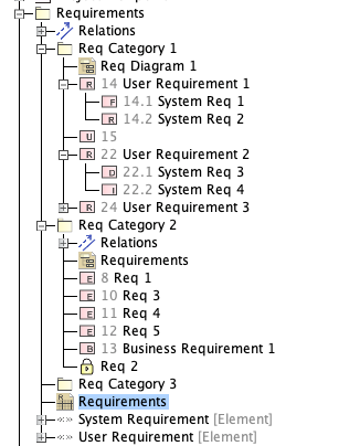
To develop a well-organized requirements model, SysML recommends the use of packages, which are are folder-like structures that contain requirements in a hierarchical manner (Figure 2). These packages can have their own internal structure that offers some relief from the complexity of the requirements. The added complexity of structures that are too deep inhibit model navigation. In most cases, three layers should be sufficient. If more layers are needed, it may be a good idea to redesign the package structure and make it wider and flatter.
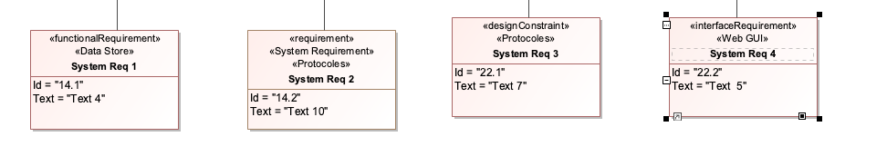
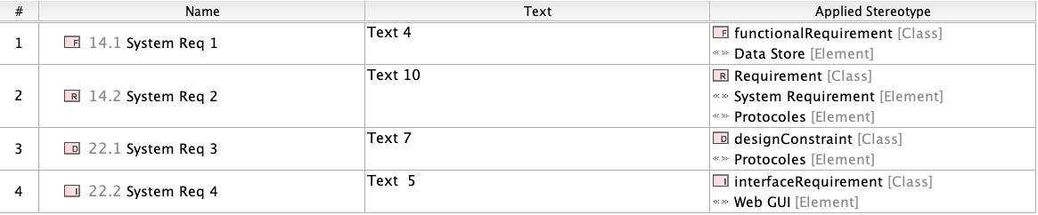
If the requirements categorization needs to have additional dimensions, the SysML stereotype element can be used. It works like a tag, but can have its own properties. If there is a need, a stereotype can be applied to a requirement (Figure 3). Later, the requirements that were stereotyped can be presented in one of the views such as a table (Figure 4), or identified across the model and shown in Used By view (Figure 5).

Requirements Traceability and Relationships
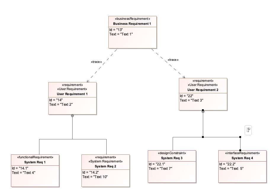
One of the most important aspects of requirements modeling is traceability to sources, to steps in the engineering process, and to elements of the system architecture. A requirement diagram enables the systems engineer to tell a story for each requirement. The diagram maps the provenance of the requirement. The diagram reveals
- in which version of the system requirements document (SRD) they were published to stakeholders
- whether other requirements were derived from them
- whether they refine any use cases
- whether they have associated test cases to be verified
- which parts of the solution architecture they satisfy
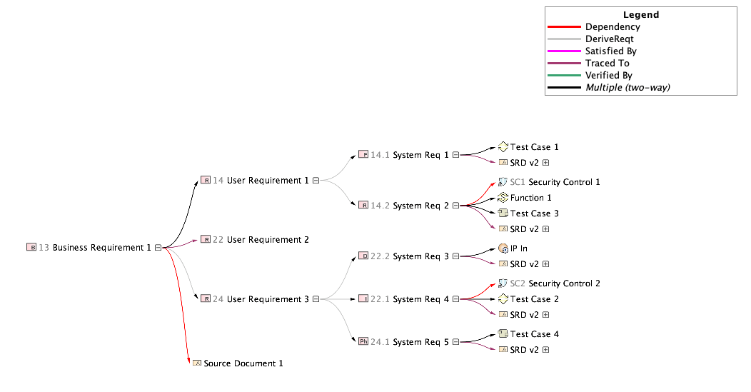
Figure 6 provides an example of the story.
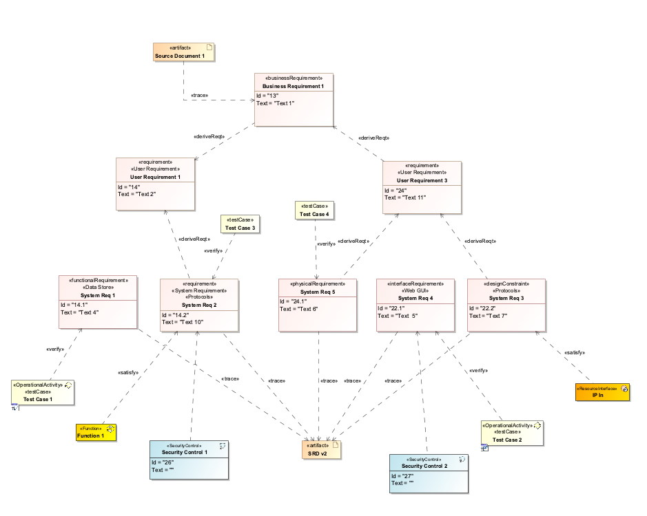
Figure 6 includes a special element type, security control. I will discuss security controls and their connection to security requirements in a future blog post.
Depending on the number of requirements and the depth of their decomposition, it may make more sense to have separate diagrams for high-level requirements and system-level requirements. High-level requirements can show only the decomposition of the requirements and traceability to source documents and SRD. System-level requirements diagrams could contain more elements and relationships, showing several requirements in the same diagram. However, such a diagram may be too busy and hard to understand.
Instead of just putting high-level requirements and system-level requirements in the same diagram, the best way to show that two objects in the model should be considered together is to create a relationship between them. If there is a relationship established between two objects in the model, the systems engineer can create a number of different views of it.
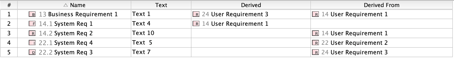
A table is a useful view of the requirements in the model. Tables can show various attributes and relationships among requirements. The table view can also be valuable for spotting errors in the model, such as a relationship created in the wrong direction.
For example, in Figure 7, I added two columns: Derived and Derived From. In row 1, Business Requirement 13 has one Derived requirement and another Derived From requirement, which means that Business Requirement 13 is derived from User Requirement 14, and User Requirement 24 is derived from Business Requirement 13. Knowing that business requirements are high level and cannot be derived from any other requirement, the Derived From column for business requirements should be empty. The table view makes this error easy to identify. The system requirement in row 2 is low level and can be derived only: The Derived column should be empty.
Analytical Tools in the Model
One of the main advantages of the model is its ability to create dependency matrices for every type of relationship. The dependency matrices are automatically updated every time a corresponding relationship changes in the model. These matrices can be used as a verification tool similar to the way tables are used to find errors in the model.
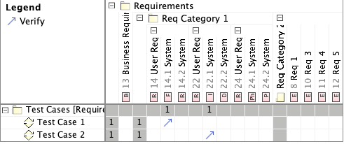
Figure 8 shows a matrix for dependencies between requirements and test-case activities that are indicated in the model by the Verify relationship. The matrix makes it easy to see which requirements are verified and which are not.
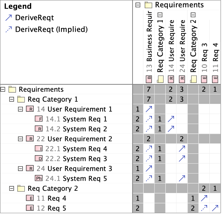
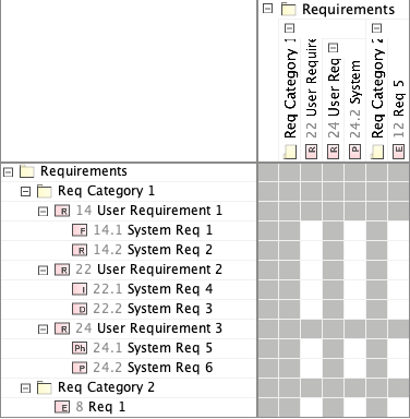
Figures 9 and 10 show another view of the Derive relationship. The difference between Figure 9 and Figure 10 is that Figure 9 shows all states of the Derive relationship in the model, whereas Figure 10 shows requirements that have no Derived From relationships. Figure 10 shows so-called "negative space," the requirements that are without the Derive relationship. This type of matrix can be helpful in identifying "orphaned" requirements, such as unmapped business requirements.
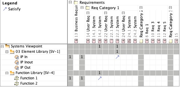
Similar to the Verify matrix, the Satisfy dependency matrix view (Figure 11) shows all Satisfy relationships within the identified scope. All matrices can show specified relationships in one or both directions, and the negative space.
Digital modeling provides us with another analytical tool--a coverage metric, which allows us to evaluate a current state of the model. In addition to calculating statistics of how many requirements are covered by test cases (Verify relationship) or design elements (Satisfy relationship), every metric records a time stamp. Periodically calculating the same metric allows the user to monitor changes of a specific aspect of the model in time, as shown in Figure 12.

Finally, I would like to mention dependency maps. Generating a dependency map for a requirement that is situated at the top of a tree gives a more comprehensive view of that tree. This map shows all types of relationships that involve a requirement at the top of the tree. It shows multiple levels of these relationships and how the requirement relates to other domains, such as testing, security, documentation, and system behavior. These various views allow us to project the impact of any changes on the top or in the middle of the tree. It also provides another view of the relationships between requirements and other elements in the model, as shown in Figure 13.
Capabilities in MBSE
In my next blog post on MBSE, I will discuss the role of capabilities in MBSE and how they can be associated with business requirements. A system's capabilities come into play when product and project managers look at the future system or existing system at the level of the system's vision and development roadmap. Focusing on capabilities affords a comprehensive view of the system that is independent of implementation details. Like requirements, capabilities are elements of the problem description; capabilities and requirements are tightly connected, and they inform and refine each other.
Additional Resources
Read the SEI blog post, An Introduction to Model-Based Systems Engineering (MBSE).
Read the SEI blog post, Modeling Capabilities with Model-Based Systems Engineering (MBSE).
Watch the SEI video, What Would Convince DoD Program Managers to Use Model-Based System Engineering?
Written By

More By The Author
More In Software Architecture
PUBLISHED IN
Software ArchitectureGet updates on our latest work.
Sign up to have the latest post sent to your inbox weekly.
Subscribe Get our RSS feedMore In Software Architecture
Get updates on our latest work.
Each week, our researchers write about the latest in software engineering, cybersecurity and artificial intelligence. Sign up to get the latest post sent to your inbox the day it's published.
Subscribe Get our RSS feed