Software Modeling: What to Model and Why


Model-based systems engineering (MBSE) environments are intended to support engineering activities of all stakeholders across the envisioning, developing, and sustaining phases of software-intensive products. Models, the machine-manipulable representations and the products of an MBSE environment, support efforts such as the automation of standardized analysis techniques by all stakeholders and the maintenance of a single authoritative source of truth about product information. The model faithfully represents the final product in those attributes of interest to various stakeholders. The result is an overall reduction of development risks.
When initially envisioned, the requirements for a product may seem to represent the right product for the stakeholders. During development, however, the as-designed product comes to reflect an understanding of what is really needed that is superior to the original set of requirements. When it is time to integrate components, during an early incremental integration activity or a full product integration, the original set of requirements is no longer represented and is no longer a valid source of test cases. Many questions arise, such as
- How do I evaluate the failure of a test?
- How can I evaluate the completeness of a test set?
- How do I track failures and the fixes applied to them?
- How do I know that fixes applied do not break something else?
Such is the case with requirements, and much the same should be the case for a set of models created during development—are they still representative of the implemented product undergoing integration?
One of the goals for robust design is to have an up-to-date single authoritative source of truth in which discipline-specific views of the system are created using the same model elements at each development step. The single authoritative source will often be a collection of requirement, specification, and design submodels within the product model. The resulting model can be used as a valid source of complete and correct verification and validation (V&V) activities. In this post, we examine the questions above and other questions that arise during development and use the answers to describe modeling and analysis activities. In particular, we will discuss
- questions that a model should address and how asking the correct questions leads to a robust design
- characteristics to look for in models to achieve a robust design
- a minimal submodel set to define the modeling chain
- what happens as a product evolves from specification to actual implementation (or operation).
A product-development process that employs MBSE creates many representations of the product under development for description and analysis. These representations bridge the gap between early product requirements and the concrete realization as executable implementations. These representations are models of the product created for description and analysis. The representations capture specific aspects of the structure and behavior of the product to aid in understanding the suitability of the product design. In this post, we will examine a number of questions related to the reasons for creating models, the selection of types of models, modeling languages, and model-evaluation criteria.
The requirements enforced at any given moment have, in many cases, evolved and diverged from earlier requirements statements. For example, consider that engineers revise, specialize, and generalize existing requirements. Along the way, tests written against the original requirements lose validity, and valuable resources must be used to revise them to regain their validity. MBSE model-development techniques produce traceability information that is useful for maintaining a valid set of requirements despite multiple development iterations that incrementally modify the requirements definitions.
Examples include the following:
- an MBSE approach that provides mechanisms for analyzing early representations of a software architecture that can determine whether critical system attributes would achieve their desired values
- an MBSE approach that provides mechanisms for analyzing more complete representations, such as the automatic generation of code directly from a comprehensive design model
An MBSE product-development effort creates a set of models of the product being developed as the basis for decision making. Decisions involve
- Should the planned product be built as a member of the product line?
- Is there a component for reuse that would satisfy these requirements?
- Are the planned computing resources (memory, throughput, bandwidth) sufficient for addressing processing and communication needs?
- What functions must occur at startup, during normal execution, and during an error or fault-correction state?
We have found that Why? is one of the fundamental questions that should be—but all too often is not—asked early and often. Project personnel should ask the purpose of each model artifact and what decisions it supports:
- Why is this model being created?
- Who will use the model?
- What other models will be derived from this model’s contents?
A related set of questions, often asked by novices, includes: How many of each type of artifact should be created? The modeling plan, described in a subsection below, provides the rationale for specific types and quantities of models. The question, How many?—as in how many sequence diagrams to use—is analogous to asking a priori how many sentences will be needed to write this blog post—a hard question to answer and ultimately of little or no use.
Modeling languages, such as Architecture Analysis and Design Language (AADL) and Systems Modeling Language (SysML), have semantics to represent the behavior and relationships of a software system. A model is a collection of representations whose contents depend on the languages and tools used. Some modeling languages have a single type of representation, usually either text-based or graphical, while others, such as AADL, have multiple representations, such as text, graphics, and XML-based representations. In some cases, the tools provide extensions to the language standard, often early versions of its next release.
The representations chosen by the engineer may have predefined rules for including models, each chosen to present a different perspective on the product. We will refer to each of these constituent models as a submodel in recognition that no single artifact, picture, or specification is sufficient. For example, a diagram showing the generalization relations among a family of blocks should be accompanied by diagrams defining the incremental definitions of behavior in those blocks. Information in a submodel should be semantically consistent with other information in the same, or even different, submodel but the information in the submodel might not be structurally consistent with the information in a different submodel.
One of the most important reasons for creating a model is to enable an analysis to answer a design or implementation question. As we investigate analysis techniques, we will provide example criteria for evaluating each technique. Three basic criteria are described in Table 1. While the criteria will remain relatively stable, the means of evaluating each criterion will vary with the situation.
Table 1 - Evaluation Criteria
|
Criterion |
Evaluation |
|
Correctness |
Analysis results conform to accepted standards. |
|
Completeness |
All analysis points have values. |
|
Consistency |
All measurements are created to the same degree of accuracy. |
There are several factors that influence the exact evolution of models for a project. Factors such as how well understood the domain is affect how detailed the domain models must be to ensure accurate communication. These decisions influence roles for stakeholders, model evolution, scope, and fidelity. We identify below some of these factors and discuss their influence on the decisions made during development.
Maturity of Stakeholders
The information needs of stakeholders influence which models are created in an MBSE project. Table 2 lists key stakeholder roles and describes the information needs of each project role. In general, stakeholders need to understand (1) what is needed by the program and what is covered in the program’s requirements, and (2) what is supported from the various suppliers’ product lines to meet the program requirements.
The stakeholder’s maturity in the domain(s) covered by the system under development will influence the scope of the domain-definition models that a stakeholder needs. The novelty of the design, from the stakeholder’s perspective, influences the number of flows that should be examined in sequence diagrams or other flow diagrams. The complexity of decision making in the system will influence the number of state machines needed to develop an understanding of the system’s proposed behavior. Organizing the model using the equivalent of architectural views enables the product model to be tailored to the individual using the model.
Table 2 - Stakeholder Roles
|
|
Information needs (questions that need answers) |
Responsibilities |
Authority |
|
Product Line (PL) Champion |
commonality/variability analysis (across all domains) |
maintain scope and focus of all PLs |
commit start-up funds |
|
PL Manager |
anticipated product needs from system acquirers |
· develop component scoping · assign and manage specification teams · work with acquirers and integrators to support use of components from each PL |
· review models used to specify components and review components developed by suppliers · reject proposed product line members that violate the scoping rules · ensure that updates are propagated to all eligible products |
|
Component Specification Modeling Team |
· component scope · vocabulary and standards-based concepts for the component domain |
· create specifications using accepted vocabulary · maintain integrity of the model chain |
develop component specification |
|
Component Supplier |
component that meets specifications |
identify or build components that conform to the specification. |
can recommend changes to specification |
|
Product Acquirer |
searches for appropriate products
|
identify or build components that conform to the specification |
can reject proposed components |
|
System Integrator |
the glue code needed to join components together |
deliver a system to the acquirer through integration of components from the marketplace along with components that are not in a marketplace product line |
can reject proposed components |
Domain/Market Maturity
The maturity of the domain influences the answers to questions such as, How frequently should the domain model be revised? The churn in a model that is not structured for flexibility and that is restructured with every release will be high. This churn is expected in component domains that do not have available implementations. In component domains where industry standards or commercial components already exist in the marketplace, the churn will be much less disruptive. For example, the FACE consortium has produced a marketplace of component interfaces and component implementations that can be used by the product acquirer to supply the system integrator.
Table 3 - Maturity Criteria
|
Name |
Criterion |
|
Correctness |
Chosen data accurately reflect current consensus. |
|
Completeness |
All analysis points have up-to-date values. |
|
Consistency |
All measurements are created to same degree of accuracy. |
|
Periodicity |
Interval between releases of standards’ versions or other authoritative sources. The shorter the period, the more rapid the need to refresh the domain models. |
Model Scope
The scope of a product line is the extent of a domain of products that is determined to be in as opposed to the portion of the body of products that is considered to be out. This determination is usually accomplished by listing constraints that give criteria for being in or out. For example, “The models and associated constraints created in a product line project are used to answer questions such as, Should this product be built as a member of a product line?”
The different submodels of the product model may cover different scopes. For example, a commonality and variability model may identify that all of the products use internal combustion engines, while a marketing model might constrain the product line to only natural gas as the type of fuel. The product line scope is determined by the conjunction of the constraints.
Three typical types of scope are product, family of products, and enterprise. This use of the term “scope” should not be confused with the scope of the product line, which is expressed in terms of deliverables.
Models, such as those for data definition, provide decision support for questions within the family and enterprise scope, while functional system interfaces provide information used to answer questions related to product scope. Context diagrams are explicit representations of scope. Constraint statements make the limits on product-line scope sufficiently explicit for quantitative analysis.
Table 4 - Example Scope
|
|
What |
When |
Why |
|
Enterprise |
reference architectures |
These architectures exist in the ecosystem of a domain prior to a specific project. |
The enterprise level provides stakeholders with rationales for the broad strategies defined at this level. |
|
Family of Systems |
architecture fragments made more specific to the projects under development |
These architectural fragments are captured as the team gains experience. |
Chosen to maximize reuse of applicable components |
|
Product |
the complete architecture of a specific application |
when product requirements model is completed. |
The product scope should exactly match a set of customer desires. |
Table 5 - Scope Evaluation Criteria
|
Name |
Criterion |
|
Correctness |
All entities referenced in the model are within the scope. |
|
Completeness |
All entities within the scope appear in the model. |
|
Consistency |
All measurements within the same scope belong to the same level of the conceptual architecture and use the same measurement units. |
Model Fidelity
Models are created with varying levels of detail. (See Architecture-Centric Virtual Integration Process [ACVIP] Management Plan for additional details.) In the initial discussions about a system capability, details are often omitted due to uncertainty or emerging knowledge. As the capability becomes more understood and more precisely defined, details are added to the models.
Several questions arise in relation to the fidelity of the model. For example, given the current fidelity of the model, how accurate are the results of attribute analyses? Is that sufficient accuracy for the intended analyses?
Table 6 - Fidelity Evaluation Criteria
|
Name |
Criterion |
|
Correctness |
The chosen level of detail is adequate to correctly execute the needed analyses. |
|
Completeness |
All model elements have a computed analysis result. |
|
Consistency |
All submodels are created to the same level of detail. |
Dependency
Models capture the information necessary to answer questions about which components depend on other components. This information is useful when performing impact analysis during change analysis. Several relationships signify a dependency between elements. We examine two of these relations as examples—traceability and generalization—below.
There are static dependencies shown in models such as class or block diagrams, which show a definitional relationship. There are also dynamic dependencies that show transient relationships such as actual parameter specifications.
Table 7 - Dependency Criteria
|
Correctness |
Every traceability relationship for an architectural element A in the model points to an architectural element B that is the basis for the definition for element A. |
|
Completeness |
The scope of the models being created matches the scope being analyzed in current iteration. |
|
Consistency |
No relationship for an architectural element A in the model can contradict the fact that A depends upon B. |
Traceability
The submodels in a product model often are produced by independent teams, and the typical questions to be answered are, Where did this come from? and How do I know this is correct? Each submodel must provide sufficient context information to allow users to trace the origins of information from one submodel to another.
The derivation of requirements in one component submodel from those in another is represented as a derived from relationship, from the new requirement to the legacy one, in whatever form relationships are represented. SysML uses trace as the name for the derived from relationship.
One typical example is the tracing among requirement models. Many projects begin with a set of user requirements. As the project creates a more detailed understanding of the problem, more detailed requirements, most of which expand on the original user requirements, are created. The relationships from the one set of requirements to another should be modeled with a trace relation. With hundreds of requirements and as many as six or seven layers of requirements, the trace relation is necessary.
The trace relation supports validating requirements by making their origin easy to identify and thereby making it easy to validate the product’s requirements. The trace relation also supports verification by facilitating the incremental creation of test cases. The tester begins the definition of a test case with a requirement. The tester then follows the traceability relation to related requirements and uses these to add detail—constraints or claims—to the test case.
Table 8 - Traceability Criteria
|
Name |
Criterion |
|
Correctness |
Every traceability relationship for an architectural element A in the model points to an architectural element B that actually is the initial point for the definition for element A. |
|
Completeness |
Every traceability relationship for an architectural element A in the model points to an architectural element B that is the initial point for the definition for element A. |
|
Consistency |
All traceability relationships use a single language construct to define the connection. |
Generalization
Development paradigms that define constructs incrementally with a generalization/specialization relation support the incremental definition of test cases.
Table 9 - Generalization Criteria
|
Name |
Criterion |
|
Correctness |
Every traceability relationship for an architectural element A in the model points to an architectural element B that actually is the initial point for the definition for element A. |
|
Completeness |
Every traceability relationship for an architectural element A in the model points to an architectural element B that is the initial point for the definition for element A. |
|
Consistency |
The template modeling language must establish rules for specialization to be followed when creating the generalization and when using the template to create an instance. |
Modeling Plan
The modeling strategy for a product includes a modeling plan that specifies a sequence of models that stakeholders in the product should build. The model of a product comprises a set of submodels, contributed by a range of stakeholders, that provide a variety of types of information from product requirements to architecture patterns to actual implementations. The artifacts are created using multiple representations of information needed to accurately construct other submodels as well as implementations of the product.
The value of the modeling plan is two-fold. First, the plan ensures that resources are used efficiently, because each model is created for a specific purpose. Second, each model contributes to achieving a robust design by covering essential facets of the product.
Model Chain
MBSE projects create a model chain—the series of models created as the project proceeds through the development-process stages (see Figure 1). Early system analyses produce a model that will form the basis for models created in later phases of the process. The submodels in this first link in the model chain include domain models, concept of operations, and others. The later models created during design and implementation have traceability and derivation relationships with earlier models and provide a chain of evidence to boost confidence in the satisfaction of attributes’ values.
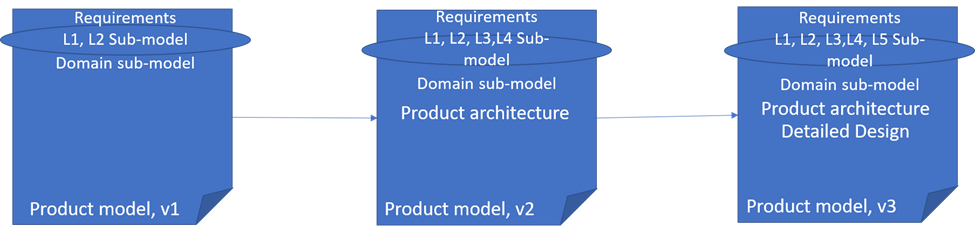
Figure 1 also shows the model-chain concept as stated above. The narrative above documenting the figure represents a chain for models. Product model, v1 shows the functional architecture, architecture requirements, and feature model content. In v2, stakeholders will see content that is related to architecture and externally visible properties that will be present in the implemented product. These properties must trace back to functional aspects of the specification, architecture requirements satisfied by the architecture, and potential variation sets satisfied by the architecture. L3 and L4 expand on the specifications captured in the v1 of the model chain. Any changes that are recognized as needed must be approved by a change board and reflected back into v1. Derived or new requirements must be similarly approved. The v3 of the product model adds to the model chain with representations that address internal detailed design.
The modeling plan describes the timing of adding each new link to the chain. It also describes the attributes of each model needed to assure that planned analyses can be conducted. The attributes to estimate are a major determinant of which submodels will be needed. For example, the prediction of how long it will take the system to perform an operation corresponds to the flow latency between two points of the architecture in the system under development. A submodel representing a use case using a sequence diagram, where the lifelines represent selected elements from the domain model, can be the basis for computing the latency of the operation.
The number of models in the chain and the exact content of each type of model is initially determined by the number and types of analyses planned in the development-process definition. Additional diagrams and other artifacts are created during informal design discussions to help explore newly conceived ideas. These obviously are not part of the model a priori plan, but they can be added to the product model as it evolves over time if they prove to be sufficiently useful. Both planned and ad hoc submodels consume considerable resources since the artifacts must be created and, in many cases, sustained.
The type and number of submodels that will be necessary and sufficient depend on the specific modeling situation being discussed. Many submodels will be created just to reject a proposed design. The modeling plan should give clear guidance on criteria to use in determining which of these submodels should be retained and which should be discarded. Models of rejected design decisions may be of use as documentation and lessons learned just as much as those submodels defined in the development plan.
Models exist to support decision making and tradeoff analyses such as determining whether specific timing requirements are being met and which of two module implementations is the most robust with respect to changes in data-packet size. A model must be constructed using a representation with sufficient semantics to express the attributes needed to support these design activities—in the examples above, execution time and byte size of data packets—and to reason about the relationships among attribute values in related components. To be meaningful in the broader development context,
- A model must be complete within the current context. Not every scenario will be modeled and analyzed, but the model should support random selection within a specified context.
- A model must be unambiguous. Each element in the modeling language must have a clear semantic.
ACVIP
The architecture-centric virtual integration process (ACVIP) is described best by considering the three parts of the name:
- Architecture-centric—ACVIP uses the architecture submodels of a product model as a surrogate for the completed product. The submodel is developed using a type of representation that has a well-defined set of semantics and that supports modeling data definitions, system structure, and behavior. In a related blog post, we briefly discuss SysML and AADL, modeling languages suitable for building architecture models for ACVIP activities. The Unified Profile for DoDAF/MODAF (UPDM) is another architecture profile from the Object Management Group related to aspects of UML and SysML.
- Virtual integration—Components that are designed and instantiated using one of the modeling languages can be joined using symbolic connections and flows forming a virtually integrated product. A tooling environment is provided that supports defining algorithms for attributes such as flow latency from one point in a product to another.
- Process—ACVIP is an ongoing series of activities that are intertwined with the product-development processes. The integration activities begin to appear much earlier in a project following ACVIP.
ACVIP is intended to mitigate several product-development issues, including measurement of runtime and performance parameters. However, the need to perform ACVIP analyses can raise questions early in a development project, such as during specification activities. Questions of a specification can include, Is the specification correct, complete, consistent, etc.? To ask the right questions, the developer must recognize that modeling is more than a description of structure, behavior, and information flow.
Models should also be analyzable and should include attributes for analysis of those submodel types to address verification and validation (V&V) of requirements. As the model chain evolves from model to model, engineers in each subsequent phase take the model chain as input, ask the appropriate questions for that point in the model chain, perform model-based validation, and create additional submodels. Every traceability relationship for an architectural element A in the model points to an architectural element B that is the initial point for the definition for element A.
ACVIP facilitates this type of analysis across the model chain. Integration and test of the model of a proposed system may occur early in the development before significant implementation of the system is completed. ACVIP combines elements of a product-development strategy such as Agile, product line, or model-based with process steps to enable modeling the product using the earliest product artifacts such as domain models and industry standards.
The Value of Model-Based Approaches
Model-based approaches have been prescribed as the approach to address various issues, such as the process and product defects arising from vague or incomplete communications and ambiguities or incompleteness in specifications. This post examines these issues and proposes modifying processes and verifying how effective they are when used to manipulate models of products. The post also describes modeling and analysis activities to support other questions and their resulting decisions that emerge from the specifications created using those models. The modeling activities are specifically examined through a sequence of models that cover specification, design, and implementation. The models are composed of components that are members of a component product line for integration into a variety of systems. The collection of these models is called a model chain in this post, reflecting the importance of connections between models and the usefulness of the information flows that link the models (one-to-one, one-to-many, or many-to-one) through the development.
Additional Resources
Read the SEI blog post, Modeling Languages for Model-Based Systems Engineering (MBSE)
Read SEI blog posts about MBSE.
Read SEI blog posts about AADL.
Written By


Get updates on our latest work.
Sign up to have the latest post sent to your inbox weekly.
Subscribe Get our RSS feedGet updates on our latest work.
Each week, our researchers write about the latest in software engineering, cybersecurity and artificial intelligence. Sign up to get the latest post sent to your inbox the day it's published.
Subscribe Get our RSS feed